ROBOT Electronics
http://www.robot-electronics.co.uk
초음파 거리 계측 모듈 SRF 시리즈
 |
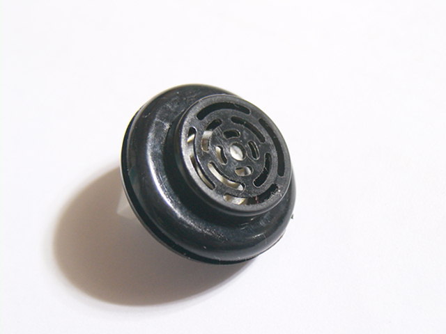
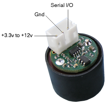
SRF-01
시리얼 인터페이스(TTL 레벨 9600BPS ) 지원 초음파 모듈
 |
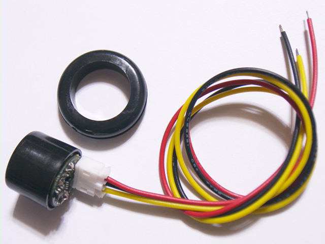 |
| Voltage - 3.3v to 12v Current - 25mA Ranging. 11mA Standby. 55uA Sleep. Frequency - 40KHz Range - 18cm to 600cm (Industrial spec', no calibration required). Range - 0cm to 600cm (Hobby spec' after auto-calibration). Connection - One Pin Serial Bus @ 9600 baud. Up to 16 SRF01's connected to a single pin on your controller. Units - Range reported in cm or inches. Very light weight, just 2.7gm Supplied with Mounting Grommet. |
 |
|
SRF-01 은 3.3V 로 동작 가능한 초음파 모듈입니다. 시리얼 로 데이터를 출력합니다. 기본 통신 속도는 9600 BPS 입니다. |
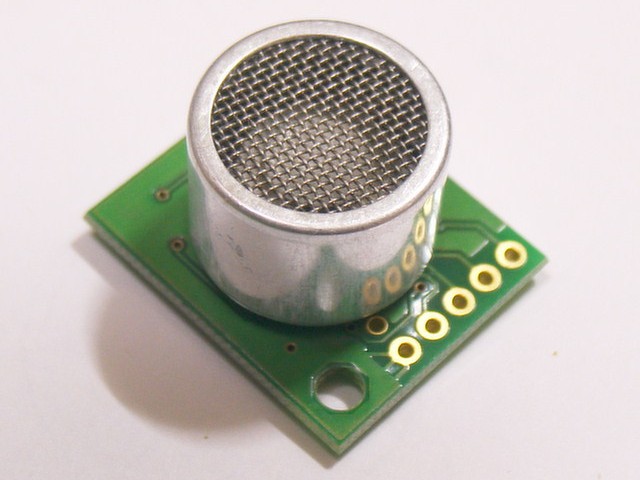
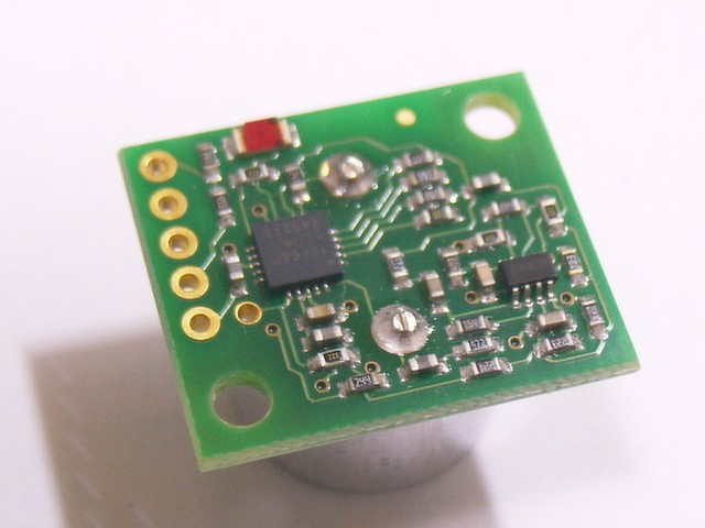
SRF02
시리얼 인터페이스(TTL 레벨) / I2C 초음파 모듈
 |
 |
|
|
|
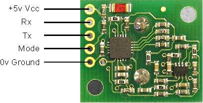
SERIAL 인터페이스 모드 : Mode Pin -> 0V(GND)
기술 사양: http://www.robot-electronics.co.uk/htm/srf02techSer.htm |
|
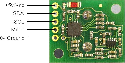
I2C 인터페이스 모드 : Mode Pin -> Open(연결하지 않음/내부 Pull-up)
기술 사양: http://www.robot-electronics.co.uk/htm/srf02techI2C.htm |
 |
| SRF-02 는 시리얼 인터페이스와 I2C 인터페이스를 지원합니다. |
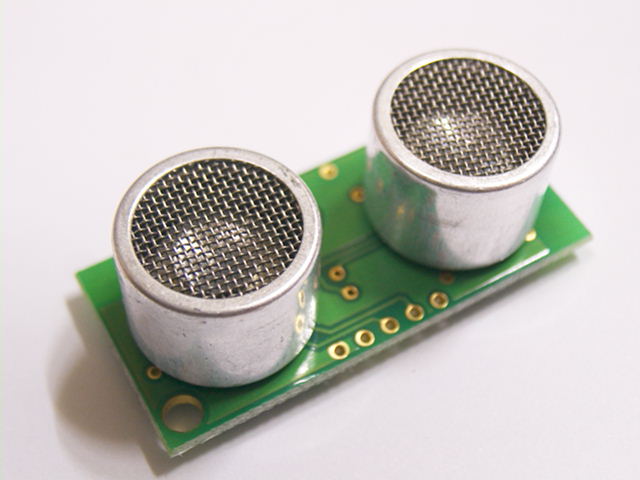
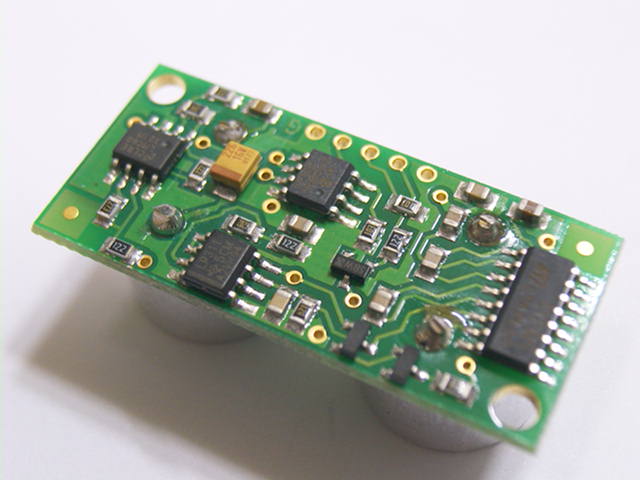
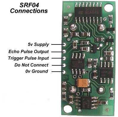
SRF04 초음파 모듈
로보틱스 업계 표준 초음파 센서
 |
 |
 |
|
SRF04 응용 예제 프로그램 |
|
|
| SRF-04 는 트리거 펄스를 입력하면 거리에 따른 펄스 폭이 출력됩니다. 마이크로 프로세서에서 타이머기능을 이용하여 펄스폭 시간을 측정한후 거리로 환산합니다. SRF-05 에 비하여 초음파 음압출력이 높습니다. |
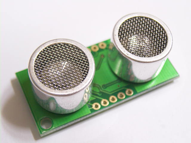
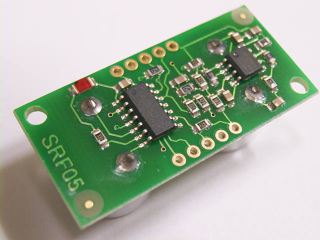
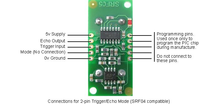
SRF05 초음파 모듈
http://www.robot-electronics.co.uk/htm/srf05tech.htm
|
|
|
|
 |
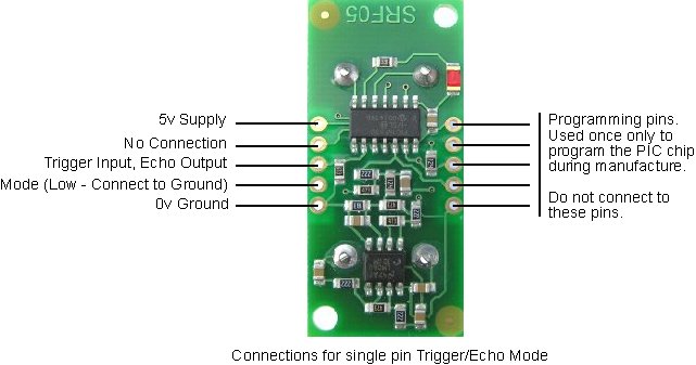 |
 |
| SRF-05 는 트리거 펄스 입력b후 거리에 비례한 펄스를 출력합니다. SRF-04 와 신호 호환됩니다. 마이크로 프로세서 포트 핀 1 개로 동작할 수 있도록 설계되어 있어 딜레이 루프에 의한 간단한 거리 측정 시 편리하게 사용할 수 있습니다. |
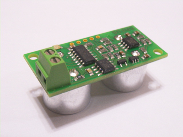
SRF06 초음파 모듈
4 ~ 20mA 전류 출력형
 |
 |
 |
 |
|
|
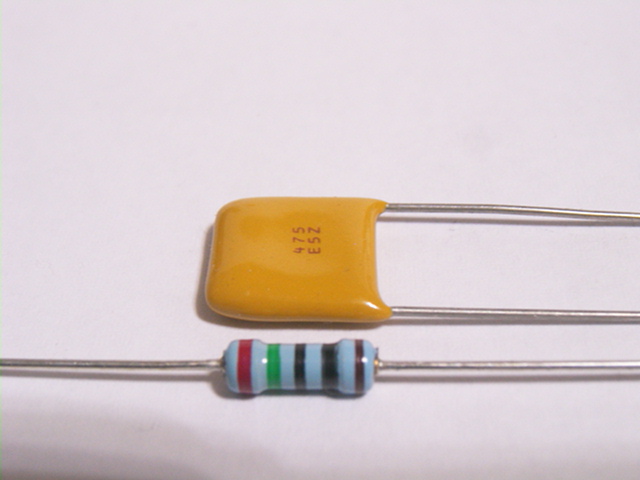
| * 70 mS ~ 100mS 주기로 연속
측정합니다. (외부 트리거 없음) * 주기 단위로 0.5V 의 노이즈 펄스가 나옵니다. 2.2uF 에서 10uF 의 캐패시터를 저항과 병열 연결하여 노이즈를 제거합니다. * 단자대 2개만 사용합니다. +12V
사용을 권장합니다. (사용범위 9V ~ 24V) |
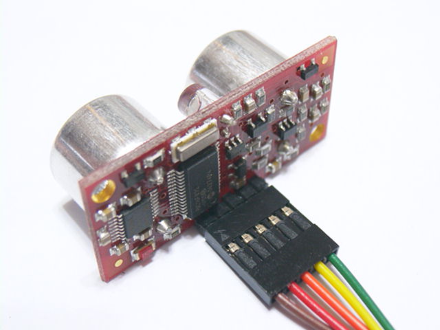
SRF08 초음파 모듈
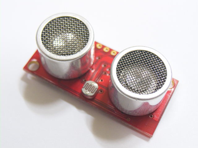 |
| SRF08은 I2C 인터페이스 방식을 사용하여 CPU 와 연결합니다. |
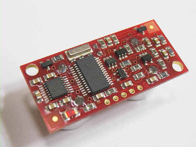 |
| 출력 데이터 형태는 CM, Inch, Time 의 3 종류가 가능합니다. |
 |
|
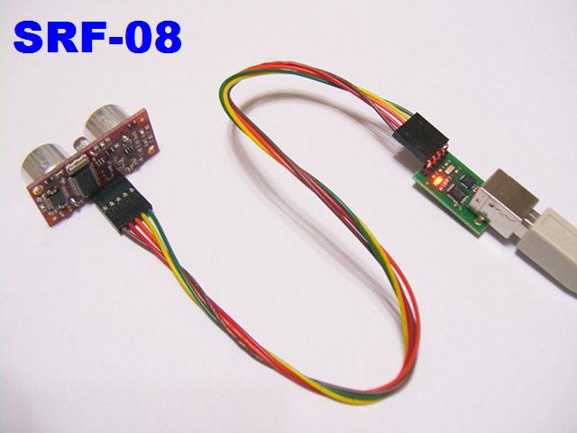 |
| SRF-08 은 I2C 인터페이스를 지원합니다. 인치, 센치, 마이크로 세커드 의 3 가지 종류로 출력 데이터 형식을 선택할 수 있습니다. |
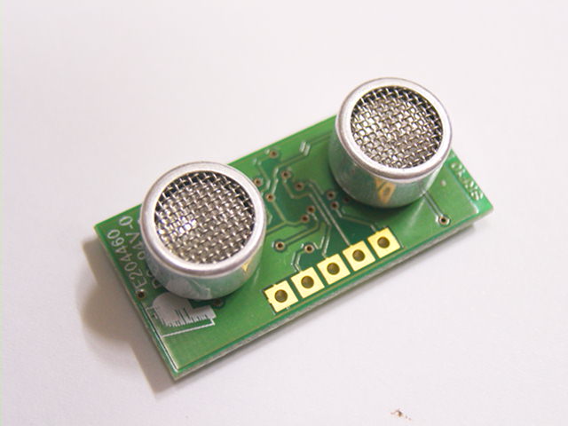
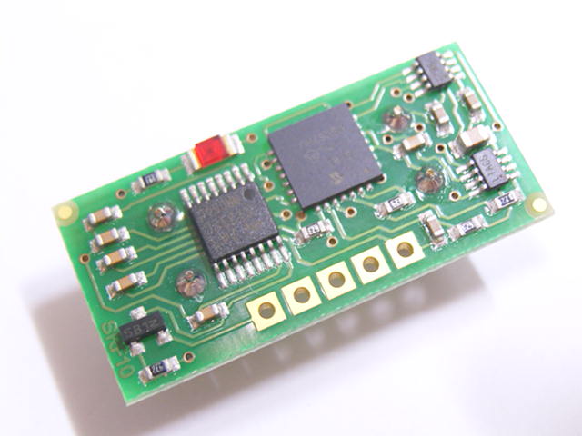
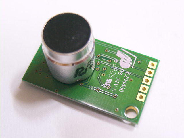
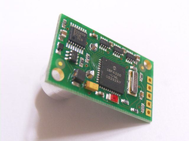
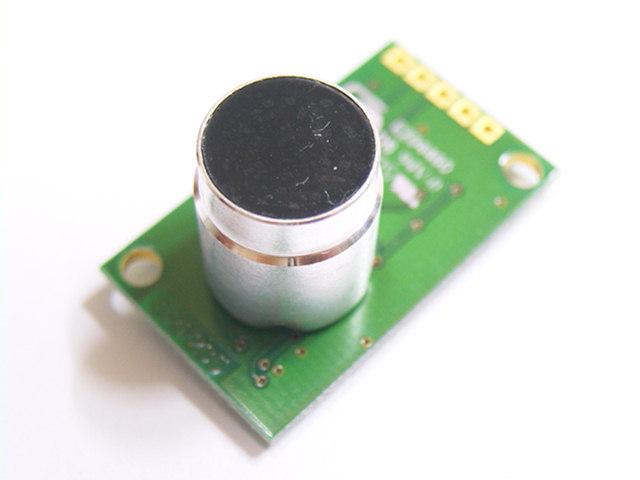
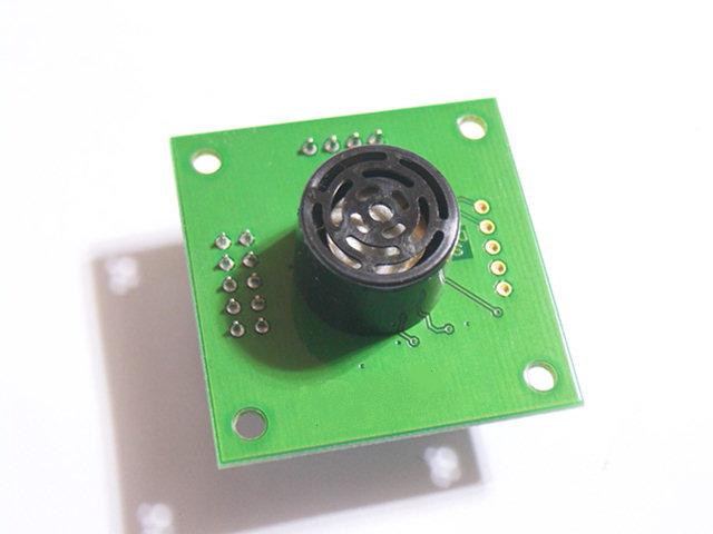
SRF10 초음파 모듈
http://www.robot-electronics.co.uk/htm/srf10tech.htm
 |
 |
|
|
|
브라킷 세트는 선택 사항 품목입니다. 서보 모터 회전판에 연결 시 사용합니다. |
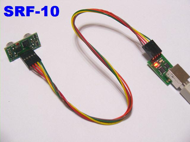 |
| SRF-10 은 I2C 인터페이스를 지원합니다. 인치, 센치, 마이크로 세커드 의 3 가지 종류로 출력 데이터 형식을 선택할 수 있습니다. |
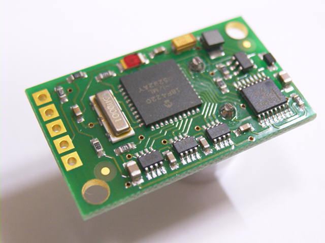
SRF235 초음파 모듈
http://www.robot-electronics.co.uk/htm/srf235tech.htm
 |
 |
 |
 |
|
|
 |
| SRF-235 은 I2C 인터페이스를 지원합니다. 인치, 센치, 마이크로 세커드 의 3 가지 종류로 출력 데이터 형식을 선택할 수 있습니다. SRF-235 는 235 KHz 의 높은 초음파 주파수를 사용합니다. 실용상 측정 거리는 최대 30 cm 이내 입니다. 측정 물체가 평면이어야 하며 초음파 진행 방향과 정확한 직각 상태를 유지 하여야 합니다. SRF-235 는 0.5mm 단위의 정밀한 위치 데이터 측정이 가능합니다. |
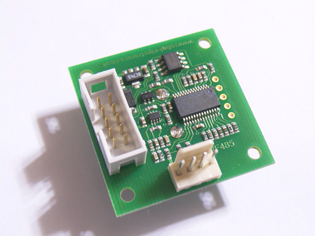
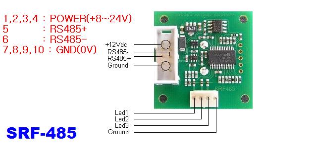
SRF485 초음파 모듈
http://www.robot-electronics.co.uk/htm/srf485tech.htm
 |
 |
 |
|
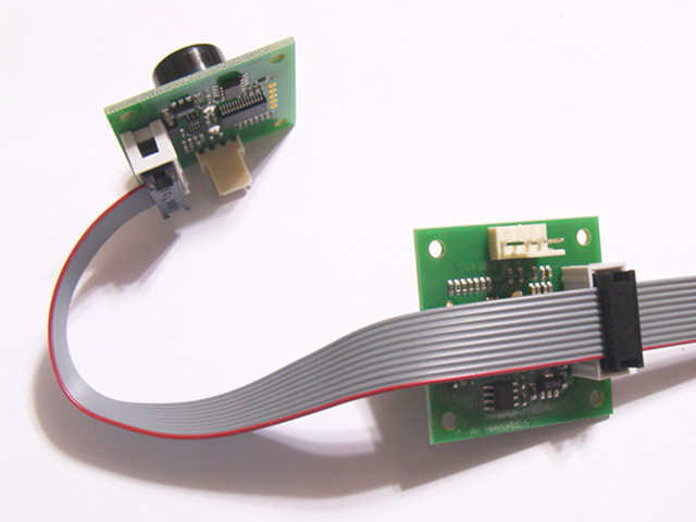
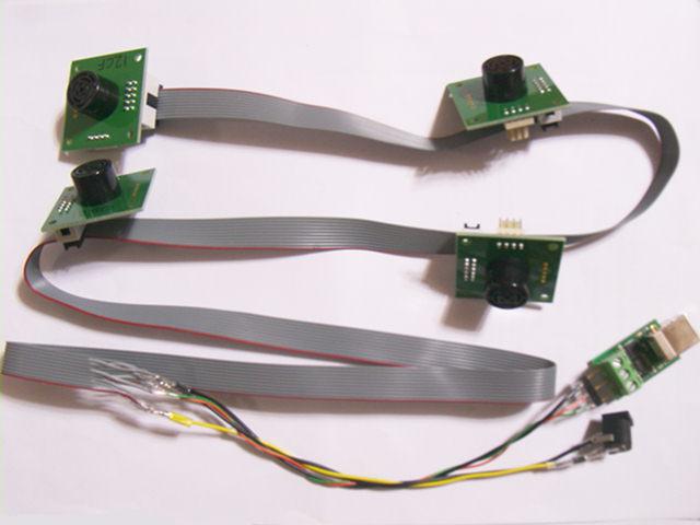
SRF485 테스트 프로그램
SRF48.ZIP : 압축을 해지하고 Release 폴더의 SRF48.exe 를 실행합니다. PC 와 UBS-485 를 연결하여 4 개의 SRF-485를 구동한 예입니다. |
 |
 |
 |
| Voltage - 8v to 24v Current - 10mA Frequency - 40KHz Range - 30cm to 500cm Connection - Standard RS485 Bus Up to 127 SRF485's connected to your controller. Units - Range reported in uS, cm or inches. Temperature Compensation -30 to +50 centigrade |
| SRF-485 는 RS-485
인터페이스를 사용하며 127 개 까지 초음파 네트웍 구성이 가능합니다. |
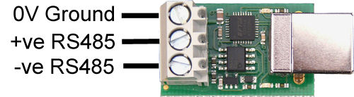
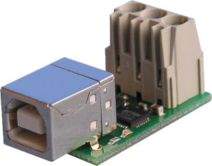
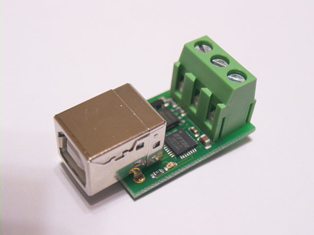
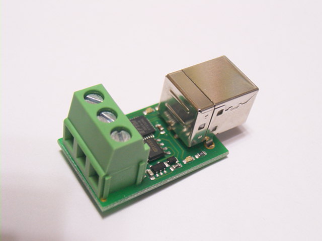
USB-RS485
 |
 |
|
|
| SRF-485 를 PC 와 연결할 때 사용합니다. |
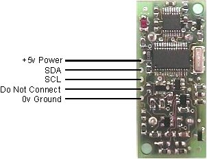
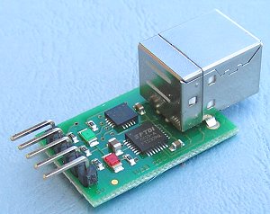
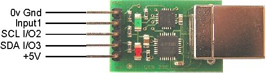
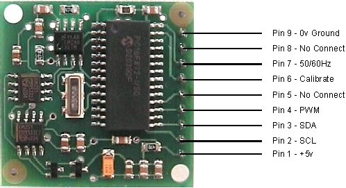
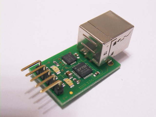
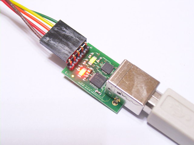
USB-I2C
 |
 |
 |
|
|
|
제조사 사용 설명서 원문 http://www.robot-electronics.co.uk/htm/usb_i2c_tech.htm
|
|
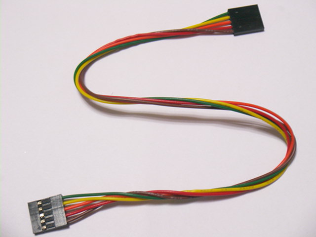
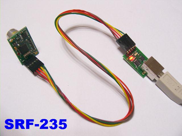
SRF-02, SRF-08, SRF-10, SRF235 와 같이 I2C
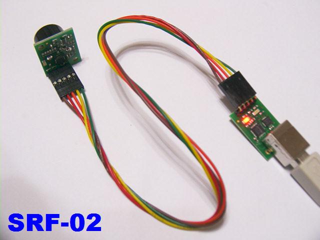
인터페이스를 사용하는 드라이버 프로그램 (타이틀에 SRF08 로 표시되어 있으나 SRF02, SRF10, SRF235 전부 사용됩니다. Light 는 SRF-08 에 광센서 데이터 값입니다. 다른 모델에서는 적용되지 않습니다. 아래의 사진을 참고하여 정확히 결선되어 있는지 확인하시기 바랍니다. 모든 것이 정상이면 초음파 센서에 부착된 적색 LED 가 초당 수회 반짝입니다. 배선의
색상 순서를 임의로 하지 마시고 사진과 |
|
|
|
|
SRF-02, SRF-08, SRF-10, SRF-235 에서 사용하는 I2C 프로토콜 인터페이스 예제
|
|
| /************************************************************************* * * * Devanteck SRF Series ULTRA SONIC SENSOR Module Demonstration Program * * * * SRF-02 * * SRF-08 * * SRF-10 * * SRF-235 * * SENSCOMP Series * * * * Witten by Junghoon Kim * * * * (c) SAMPLE Electronics co. 09 March 2004 * * * *+---------------------------------------------------------------------+* *|Speed Of Sound |* *| |* *|The speed of sound at 20 deg is 343.2 m/s(1125 ft/s). It varies only |* *|slightly with humidity (max. 0.35% at 20 deg C) and is virtually |* *|independent of pressure and, thus, of height above sea level. |* *| |* *|Only temperature has some influence:331.3 m/s at 0 deg C , 347.7 m/s |* *|at 40 deg C; i.e., 7% variation from 0 deg to 40 deg. Variation |* *|with frequency is negligible. |* *| |* *| ----- POLAROID ULTRASONIC RANGING SYSTEM HANDBOOK ----- |* *| APPLICATION NOTES/TECHNICAL PAPERS |* *+---------------------------------------------------------------------+* * * * * * * * $Rxx<CR> Requst Ranging Data * * $050<CR> Ranging Mode - Results in inches * * $051<CR> Ranging Mode - Results in centimeters * * $052<CR> Ranging Mode - Results in micro-seconds * * $053<CR> ANN Mode - Results in inches * * $054<CR> ANN Mode - Results in centimeters * * $055<CR> ANN Mode - Results in micro-seconds * * $1xx<CR> Set Gain Register * * $2xx<CR> Set Range Register * * $6xx<CR> Set Denumerator Constant in mili meter display * * $7xx<CR> Set Numerator Constant in mili meter display * * $8xx<CR> Set SRF-xx Base Address * * $9xx<CR> Change I2C Address * * * * * * * * (1) If SMOD == 0 * * (CLOCK) * * TH1 = 256 - -------------- * * (384 x BAUD) * * * * (2) If SMOD == 1 * * (CLOCK) * * TH1 = 256 - -------------- * * (192 x BAUD) * * * * * * ex) Xtal Frequency = 12MHz, Baud Rate = 4800 Bps -> TH1 = 0xF3 * * * * * * SIG - Signal Type * * P2.7 * * 0 : I2C Bus Type - SRF-02, SRF-08, SRF-10, SRF-235 * * 1 : Pulse Width Type - SRF-04, SRF-05, SENSCOMP * * * * DU - Display Mode * * P2.6 P2.5 * * 0 0 : Micro Second Display * * 0 1 : Milli Meter Display * * 1 0 : Inches Display * * 1 1 : Centi Meter Display * * * * --- Conversion and Display Mode --- * * SIG DU1 DU0 * * 0 0 0 : Non Conversion Micro Second Display I2C Bus * * 0 0 1 : Conversion Milli Meter Display I2C Bus * * 0 1 0 : Non Conversion Inches Display I2C Bus * * 0 1 1 : Non Conversion Centi Meter Display I2C Bus * * 1 0 0 : Non Conversion Micro Second Display Pulse Width * * 1 0 1 : Conversion Milli Meter Display Pulse Width * * 1 1 0 : Conversion Inches Display Pulse Width * * 1 1 1 : Conversion Centi Meter Display Pulse Width * * * * * * PWO - Pulse Width Offset * * P2.6 * * 0 : SENSCOMP Series Offset * * 1 : SRF-04, SRF-05 Offset * * * * * * THL - Threshold Level * * P2.3 * * 0 : Shumitte * * 1 : No Shumitte * * * * FLT - Filter Level * * P2.2 * * 0 : Filter * * 1 : No Filter * * * * CPM - Comparator Mode * * P2.1 * * 0 : Level Mode * * 1 : Sandwitch Mode * * * * PGM - Program * * P2.0 * * 0 : Program Mode * * 1 : Operation Mode * * * * * * * * +------------------------------------------------------------------+ * * | UST DU1 DU0 OFS THL FTL CPM PGM | * * | 7 6 5 4 3 2 1 0 | * * +------------------------------------------------------------------+ * * * * * * * * * * * * C-18 P1-fl. Main-bd. ET-LAND * * 16-9 Hangangno-3ga Yongsan-gu * * SEOUL 140-879 South KOREA * * TEL: +82-2-701-8051 * * FAX: +82-2-701-8058 * * Email: sample@korea.com * * Web: HTTP://WWW.SAMPLE.CO.KR * * * *************************************************************************/ #include <sfr.h> #include <os.h> ////////////////////////////////////////////// // 7 Segment LED 패턴 데이터 // hgfedcba #define DIG0 0xC0 // 11000000b ; 0 Px.0 #define DIG1 0xF9 // 11111001b ; 1 +-----a-----+ #define DIG2 0xA4 // 10100100b ; 2 | | #define DIG3 0xB0 // 10110000b ; 3 Px.5 f b Px.1 #define DIG4 0x99 // 10011001b ; 4 | | #define DIG5 0x92 // 10010010b ; 5 | Px.6 | #define DIG6 0x82 // 10000010b ; 6 +-----g-----+ #define DIG7 0xD8 // 11011000b ; 7 | | #define DIG8 0x80 // 10000000b ; 8 Px.4 e c Px.2 #define DIG9 0x98 // 10011000b ; 9 | | // ; | Px.3 | #define DIGM 0xBF // 10111111b ; - +-----d-----+ * h Px.7 #define DIGP 0x7F // 01111111b ; . #define DIGB 0xFF // 11111111b ; "Blank" #define ON 0 // 8051 Port On #define OFF 1 // 8051 Port Off #define TRUE 1 // #define FALSE 0 // #define I2C_DELAY 1 // #define ACK 1 // I2C Acknowlwdge #define NACK 0 // I2C Acknowlwdge ////////////////////////////////////////////// _sfrbit FNDSEL0 = _p1^3; // Select 0 _sfrbit FNDSEL1 = _p1^4; // Select 1 _sfrbit FNDSEL2 = _p1^5; // Select 2 _sfrbit FNDSEL3 = _p1^6; // Select 3 _sfrbit FNDSEL4 = _p1^7; // Select 4 ////////////////////////////////////////////// _sfrbit RELAY = _p3^5; // Relay _sfrbit SDA = _p3^6; // SDA _sfrbit SCL = _p3^7; // SCL _sfrbit TRIG_SRF = _p1^0; // Triger for SRF-04, SRF-05 _sfrbit TRIG_SC = _p1^2; // Triger for SENSCOMP ////////////////////////////////////////////// unsigned char fnd_state; unsigned char fnd[5]; unsigned char mfnd[5]; unsigned char cmd_buffer[5]; unsigned char srf_address; unsigned char new_srf_adrs; unsigned char command; unsigned char max_gain; unsigned char range_reg; unsigned char numerator; unsigned char denumerator; unsigned char display_mode; unsigned char offset_msb; unsigned char offset_lsb; unsigned char config; bit cmd_flag; bit xout_flag; ////////////////////////////////////////////// const char segment_pattern[] = { DIG0, DIG1, DIG2,\ DIG3, DIG4, DIG5, DIG6, DIG7, DIG8, DIG9 }; ////////////////////////////////////////////// void _interrupt IVN_TIMER0 time_base() { // Timer 0 Interrupt Service _tl0 = 0x18; _th0 = 0xFC; // 1000 1 mSec / 12 MHz Xtal ////////////////////////////////////////////// FNDSEL0 = OFF; FNDSEL1 = OFF; FNDSEL2 = OFF; FNDSEL3 = OFF; FNDSEL4 = OFF; _p0 = fnd[fnd_state]; if (fnd_state == 0) FNDSEL0 = ON; if (fnd_state == 1) FNDSEL1 = ON; if (fnd_state == 2) FNDSEL2 = ON; if (fnd_state == 3) FNDSEL3 = ON; if (fnd_state == 4) FNDSEL4 = ON; fnd_state++; if(fnd_state>4) { fnd_state = 0x00; } } /////////////////////////////////////////////////////////// void _interrupt IVN_SERIALPORT _using 2 _SerialInterrupt() { if (_ri) { _ri = 0; if (cmd_flag==0) { cmd_buffer[0] = cmd_buffer[1]; cmd_buffer[1] = cmd_buffer[2]; cmd_buffer[2] = cmd_buffer[3]; cmd_buffer[3] = cmd_buffer[4]; cmd_buffer[4] = _sbuf; } if ((cmd_buffer[0]=='$') && (cmd_buffer[4]==0xD)) { cmd_flag = 1; } } else if (_ti) { // transmit interrupt if here _ti = 0; xout_flag = FALSE; } } ///////////////////////////////////////////// void delay(unsigned long int i) { while(i--); } //////////////////////// I2C Routine /////////////////// void i2c_delay(void) { unsigned char i; i = I2C_DELAY; while(i--); } void i2c_start(void) { SDA = 1; // i2c start bit sequence i2c_delay(); SCL = 1; i2c_delay(); SDA = 0; i2c_delay(); SCL = 0; i2c_delay(); } void i2c_stop(void) { SDA = 0; // i2c stop bit sequence i2c_delay(); SCL = 1; i2c_delay(); SDA = 1; i2c_delay(); } void i2c_tx(unsigned char d) { // I2C Byte Write Sequence char x; for(x=8; x; x--) { if(d&0x80) SDA = 1; else SDA = 0; SCL = 1; i2c_delay(); d <<= 1; SCL = 0; i2c_delay(); } SDA = 1; SCL = 1; i2c_delay(); SCL = 0; i2c_delay(); } unsigned char i2c_rx(char ack) { // I2C Byte Read Sequence char x, d=0; SDA = 1; for(x=0; x<8; x++) { d <<= 1; SCL = 1; i2c_delay(); if(SDA) d |= 1; SCL = 0; i2c_delay(); } if(ack) SDA = 0; else SDA = 1; SCL = 1; i2c_delay(); SCL = 0; SDA = 1; i2c_delay(); return d; } //////////////////////////////////////////////////////// void put(unsigned char c) { while (xout_flag); // wait for previous byte to complete _sbuf = c; xout_flag = TRUE; } void data_out(unsigned char c) { unsigned char d; d = c; d >>= 4; d &= 0x0F; d |= 0x30; if (d > '9') { d += 0x07; } put(d); d = c; d &= 0x0F; d |= 0x30; if (d > '9') { d += 0x07; } put(d); } void set_max_gain_register(void) { i2c_start(); i2c_tx(srf_address); i2c_tx(0x01); i2c_tx(max_gain); i2c_stop(); } void set_range_register(void) { i2c_start(); i2c_tx(srf_address); i2c_tx(0x02); i2c_tx(range_reg); i2c_stop(); } void set_new_srf_address(void) { i2c_start(); i2c_tx(srf_address); i2c_tx(0x00); i2c_tx(0xA0); i2c_tx(0xAA); i2c_tx(0xA5); i2c_tx(new_srf_adrs); i2c_stop(); srf_address = new_srf_adrs; } void main(void) { unsigned char t0,t1,t2,t3,b0; unsigned char boat; unsigned long int trailer; unsigned long int table; _tmod = 0x21; // Timer0 = Mode1, Timer, use TR0 // Timer1 = 8 Bit Auto reloaded Timer/Counter _tl0 = 0xFF; _th0 = 0xFF; _scon = 0X50; // SCON serial port control - 8 bit uart (1 stop bit) _tl1 = 0XF3; // Timer1 lo _th1 = 0XF3; // 2400 baud (12.000MHz) _pcon |= 0X80; // 4800 baud (SMOD == 1) _tmod = 0X20; // 8 bit autoreload for timer 1 ( baud rate generator) _tcon = 0; _tr1 = 1; // start baud rate generator _es = 1; // enable serial port interrupts _tr0 = 1; // Timer 0 동작시작 _et0 = 1; // 타이머 0 인터럽트 가능상태 설정 _c_t2 = 0; // Counter Mode _cp_rl2 = 1; // _exen2 = 1; _ea = 1; // 글로벌 인터럽트 가능상태 설정 command = 0x51; // Default 0x51 max_gain = 0x00; // Max Gain Register range_reg = 0x00; // Range Register denumerator = 0x00; // Denumeraator numerator = 0x00; // Numerator srf_address = 0xE0; // Default SFR-xx Base Address cmd_flag = 0; // Clear command flag xout_flag = 0; // Buffer out flag TRIG_SRF = 0; TRIG_SC = 0; config = _p2; // Configuration DIP Switch boat = config & 0x60; command = 0x52; // Default Micro Second Display if (boat == 0x60) { command = 0x51; // Centi Meter Display } if (boat == 0x40) { command = 0x50; // Inches Display } while(1) { if (cmd_flag) { if (cmd_buffer[3] > '9') { cmd_buffer[3] -= 0x07; } cmd_buffer[3] &= 0x0F; if (cmd_buffer[2] > '9') { cmd_buffer[2] -= 0x07; } cmd_buffer[2] <<= 4; cmd_buffer[2] &= 0xF0; boat = cmd_buffer[2] | cmd_buffer[3]; if (cmd_buffer[1]=='0') { command = boat; } // 0x50 - inches, 0x51 - centi-meters, 0x52 - micro-seconds if (cmd_buffer[1]=='1') { max_gain = boat; } // Set Gain Register if (cmd_buffer[1]=='2') { range_reg = boat; set_range_register(); } // Range Register if (cmd_buffer[1]=='O') { offset_msb = boat; } // Range Offset MSB if (cmd_buffer[1]=='P') { offset_lsb = boat; } // Range Offset LSB if (cmd_buffer[1]=='M') { display_mode = boat; } // FND Display mode: 0x00 - unmodified, 0x01 - modified if (cmd_buffer[1]=='D') { denumerator = boat; } // Denumerator Constant in mili meter display if (cmd_buffer[1]=='N') { numerator = boat; } // Numerator Constant in mili meter display if (cmd_buffer[1]=='A') { srf_address = boat; } // Set SRF-xx Base Address if (cmd_buffer[1]=='S') { new_srf_adrs = boat; set_new_srf_address(); } // Change I2C Address cmd_flag = 0; } _tr2 = 0; TRIG_SRF = 1; i2c_start(); i2c_tx(srf_address); i2c_tx(0x00); i2c_tx(command); i2c_stop(); _tl2 = 0; _th2 = 0; _tf2 = 0; _tr2 = 1; TRIG_SRF = 0; TRIG_SC = 1; /////////////////////////////////////////////////////////////////// delay(8000); /////////////////////////////////////////////////////////////////// TRIG_SC = 0; i2c_start(); i2c_tx(srf_address); i2c_tx(0x00); i2c_start(); boat = srf_address | 0x01; i2c_tx(boat); t0 = i2c_rx(ACK); t1 = i2c_rx(ACK); t2 = i2c_rx(ACK); // MSB SRF-02, SRF-08, SRF-10, SRF-235 t3 = i2c_rx(NACK); // LSB i2c_stop(); if (config & 0x80) { // SRF-04, SRF-05, SENSCOMP Series t2 = _rldh; // MSB SRF-04, SRF-05, SENSCOMP t3 = _rldl; // LSB } trailer = t2; trailer = trailer * 256 + t3; boat = config & 0xE0; // Display Window if (boat == 0x00) { ; } // Non Conversion Micro Second Display I2C Bus if (boat == 0x20) { // Conversion Milli Meter Display I2C Bus trailer = trailer * 1716 / 10000; } if (boat == 0x40) { ; } // Non Conversion Inches Display I2C Bus if (boat == 0x60) { ; } // Non Conversion Centi Meter Display I2C Bus if (boat == 0x80) { ; } // Non Conversion Micro Second Display Pulse Width if (boat == 0xA0) { // Conversion Milli Meter Display Pulse Width trailer = trailer * 1716 / 10000; } if (boat == 0xC0) { // Conversion Inches Display Pulse Width trailer = trailer * 1716 / 254000; } if (boat == 0xE0) { // Conversion Centi Meter Display Pulse Width trailer = trailer * 1716 / 100000; } if (trailer > 500) { RELAY = ON; } else { RELAY = OFF; } boat = trailer % 10; mfnd[4] = segment_pattern[boat]; trailer /= 10; boat = trailer % 10; mfnd[3] = segment_pattern[boat]; trailer /= 10; boat = trailer % 10; mfnd[2] = segment_pattern[boat]; trailer /= 10; boat = trailer % 10; mfnd[1] = segment_pattern[boat]; trailer /= 10; boat = trailer % 10; mfnd[0] = segment_pattern[boat]; trailer /= 10; boat = config & 0x60; // Display Window if (boat == 0x20) { mfnd[1] &= DIGP ; } // Milli Meter Display I2C Bus if (boat == 0x40) { mfnd[4] &= DIGP ; } // Inches Display I2C Bus if (boat == 0x60) { mfnd[2] &= DIGP ; } // Conversion Centi Meter Display I2C Bus fnd[0] = mfnd[0]; // Most Signeficant Digit fnd[1] = mfnd[1]; // & DIGP; fnd[2] = mfnd[2]; fnd[3] = mfnd[3]; fnd[4] = mfnd[4]; data_out(t0); data_out(t1); data_out(t2); data_out(t3); put(0x0D); // Carriage Return put(0x0A); // Line Feed } } /////////////// EOF ////////////////////////// |
영문 음성합성 모듈 SP03
SP03은 영어 단어(ASCII Code)를
입력하면 오디오 신호로 출력하는 음성합성기 입니다.
단순히 미리 녹음한 음성을 출력하는 것이
아니며 알파벳을 조합하여
영어에 가까운 음성을 출력합니다. SP03은
단어의 제한이 없으므로
웹페이지, 이메일의 영어 출력기, 화상 인식 시스템과 조합하여
영문서를
음성으로 변환하는 장비에 사용할 수 있습니다.
 |
| CP03 은 영문자를 음성으로 변환하는 음성 합성기 모듈 입니다. |
 |
| 4CM 의 스피커가 부착되어 있습니다. |
 |
| 음성합성 칩은 Winbond 사의 WTS701 (영어판)입니다. |
 |
| CP03에는 오디오 앰프 LM386이 내장되어 있습니다. |
 |
| CP03은 시리얼 드라이버가 내장되어 PC 의 시리얼 포트로 직접 연결가능합니다. |
SP03의 커넥터
PC 의 시리얼 포트로 연결
|
음성합성 예: (아래 예제를
클릭하면 음성을 들을 수 있습니다.)
|
SP03 은 영어 합성 모듈이지만
미국 사람식 한글 발음도 가능합니다. 예제1: "웰컴투 샘플 일렉트로닉스 반갑습니다" 예제2: "정말 감사합니다" 예제3: "오 서 오시 요" 예제4: "안녕히 가시요 잘 가시요 또 오시요" 예제5: "샘플전자 전화번호는 칠 공 일 팔 공 오 일 입니다"
|
| 관련 자료 다운로드 SP03 프로그램 소프트웨어 SP03.exe ROBOT Electronics사의 음성합성 모듈 SP03 사용설명서(영문)
|
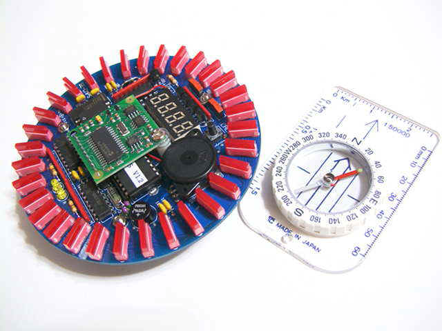
전자 나침반 / Compass Module
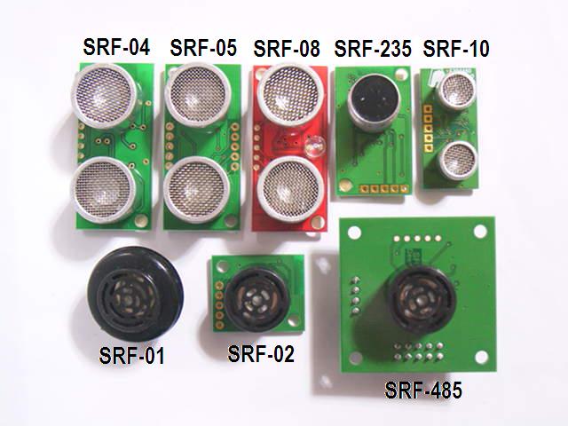
| 품 목 | 사 양 | |
| SRF-01 | 시리얼 인터페이스 | |
| SRF-02 | I2C, 시리얼 인터페이스 | |
| SRF-04 | 5 Cm - 2.4 Meter, 센서지름 16mm | |
| SRF-05 | 트리거, 에코 겸용, 센서지름 16mm | |
| SRF-08 | I2C 인터페이스, CDS센서, 센서지름 16mm | |
| SRF-10 | I2C 인터페이스, 센서지름 10mm | |
| SRF235 | 근접, 정밀측정 | |
| CMPS03 | 전자 나침판 3도 정밀도 0.1도 분해능 | |
| SP03 | 음성합성 모듈 | |
| ***
초음파모듈은 전원을 반대로 연결하면 파손됩니다. *** I2C 프로토콜 서브루틴을 가지고 있을 때 SRF-02, SRF08, SRF10, SRF235을 사용합니다. I2C는 데이터 시트를 보고 프로그래밍할 수 있을 정도로 간단하지 않습니다. 신호사양을 정확히 숙지하시기 바랍니다. 샘플전자를 경유하여 판매된 초음파 모듈은 포장이 개봉되지 않은 상태에서 환불이나 교환이 가능합니다. |
||
| SRF-02, SRF-08, SRF-10, SRF-235 에 사용되는 I2C 프로토콜 인터페이스 예제 C 소스 입니다. 8051 프로세서용 이므로 AVR 등에서는 Port 설정을 수정하여야 합니다. | ||
 |
||